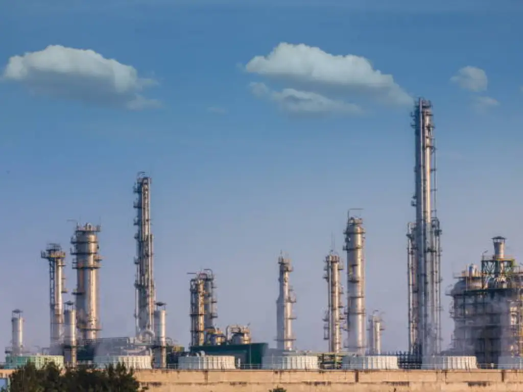
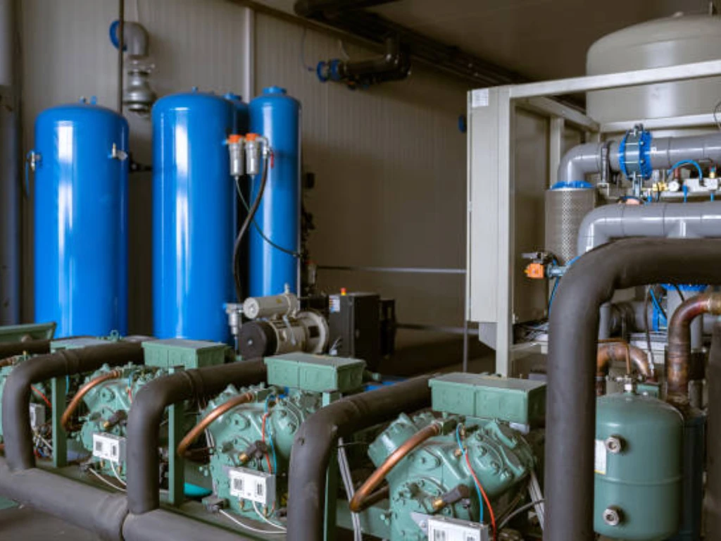
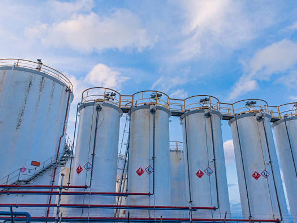
In the medium to large-scale operations, cryogenic air separation technologies are frequently utilized to create nitrogen, oxygen, and argon as gases and/or liquid outputs.
For manufacturing ultra-pure oxygen and nitrogen, cryogenic air separation is the recommended method. For high-manufacturing-rate facilities, it is the most economical technique. Cryogenic technology is used in all operations that produce liquefied industrial gas commodities.
The amount of gaseous and liquid outputs to be generated, their needed product purities, and needed delivery pressures all affect the intricacy of the cryogenic air separation procedure, as well as the physical sizes of gear and the energy needed to run it.
This article entails the process guide to cryogenic Air separation. Let’s Get to it!
What is Cryogenic Air Separation and Distillation?

The technique of separating Nitrogen and Oxygen from the air is known as cryogenic distillation. Argon is also isolated in some circumstances. The term “cryogenic” refers to cold temperatures, while “distillation” refers to the uncoupling of elements from a combination using the boiling point of the elements. As a result, constituents with very low boiling points are extracted preferentially at low temps in cryogenic distillations. This process yields high-purity substances, but it is also highly energy-intensive.
The cold box is a huge insulated container that houses the distillation pillars and heat exchangers that work at extremely low temps. The Joule Thomson effect, also known as the throttling effect, is used in the refrigeration loop. The gas passes via an insulated gate or an insulated permeable plug throughout throttling, and the temp of the gas changes as the pressure alternates.
Materials you need
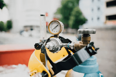
Ambient air can comprise up to 5% moisture by content and a variety of other gases (typically in trace levels) that must be eliminated at one or more locations in the air separation and output purification setup.
Steps and Process of Cryogenic air separation

Cryogenic Distillation of Air: Stages
- Incoming air pretreating, compression, and cooling.
- Eliminating Carbon Dioxide.
- Heat conduction to get the air feed temperature down to cryogenic levels.
- Air distillation.
- Refrigeration
1. Incoming Air Pretreating, Compression, and Cooling

Based on the planned product blend and acceptable product force, the air is constricted to between 5 and 8 bar (about 75 to 115 psig) in most circumstances. After the last stage of compression, the constricted air is chilled, and much of the vapour in the airflow is condensed and eliminated, as the air goes through a succession of interphase coolers and an aftercooler.
Since the temp of the obtainable cooling channelling (which is almost always restricted by the moist or dry bulb temp of the ambient air) determines the last temp of the air departing the compression structure, the temp of the compressed air is frequently well above the ideal temp for maximum effectiveness of downstream unit performances. As a result, a mechanical refrigeration system is frequently used to cool the air significantly.
2. Eliminating Carbon Dioxide and Other Impurities
To achieve product quality criteria, certain elements of the incoming airflow must be eliminated. Water vapour and carbon dioxide should be eliminated from the air before it enters the cryogenic distillation section of the plant since they would solidify and accumulate on the exterior of the procedure equipment at extremely low temps.
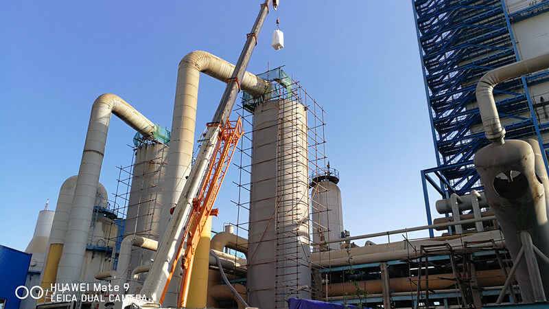
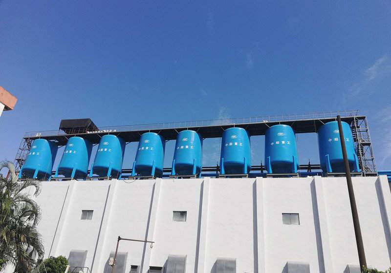
Molecular sieve units and reversing exchangers are the two most used methods for eliminating vapour and carbon dioxide.
- A molecular sieve pre-purification unit is used in almost all new air disconnection facilities to extract carbon dioxide and water from the airflow by adsorbing these particles onto the exterior of molecular sieve substances at near-ambient temp. Other pollutants, such as hydrocarbons, that may be encountered in an industrial setting can be easily removed by adjusting the composition of adsorbent substances in these systems. The adsorbent substances are usually kept in two identical containers, one of which is utilized to purify the entering air and the other of which is regenerated with clean waste gas. At regular periods, the two sheets switch service. When a high nitrogen extraction ratio is sought, molecular sieve pre-purification is the obvious choice.
- The other option is to eliminate water and CO2 using “reversing” heat exchangers. While reverse exchangers are frequently considered as “ancient” technology, they might be more cost-efficient for nitrogen or oxygen plants with lower manufacturing rates. The compressed air supply is cooled in two pairs of brazed aluminium heat exchangers in plants that use reversing heat exchangers.
Arriving air is cooled in “warm end” heat transfer to a temp low enough for water vapour and carbon dioxide to solidify on the heat exchanger’s surfaces. A system of valves alternates the duty of the air and waste gas passageways at regular intervals. Following the transition, the very dry, differentially heated waste gas evaporates the water and sublimes the carbon dioxide frost that formed during the air cooling interval. These gases are released back into the atmosphere, and the reversing heat exchanger is prepared for another reversal of transit duty after they have been completely eliminated.
Cold absorption systems are used when reverse heat exchangers are utilized to eliminate any hydrocarbons that make their way into the distillation units. (In the Pre-Purification Units, hydrocarbon pollutants are eliminated along with water vapour and carbon dioxide when a molecular sieve “front end” is utilized.).
3. Heat Conduction to Get the Air Feed Temperature Down to Cryogenic Levels

The heat is exchanged between the entering air feed and the cold output and waste gas flow leaving the cryogenic distillation procedure in brazed aluminium heat exchangers. The outgoing gas channels are reheated to a temp close to that of ambient air. The quantity of refrigeration that needs to be generated by the facility is reduced by recovering refrigeration from gaseous product channels and waste streams.
A refrigeration technique that incorporates the growth of one or more enhanced pressure steps streams produces the extremely cold temp required for cryogenic distillation.
4. Air Distillation

Two distillation pillars are used in succession to produce oxygen as a byproduct in the distillation system. The “high” and “low” tension pillars (or, alternately, the “lower” and “upper” pillars) are the most generally used terms. Nitrogen facilities can have one or two columns, depending on their purity. Each distillation pillar lets nitrogen out at the top and oxygen out at the bottom. When the contaminated oxygen produced in the first (higher pressure) pillar is a desired product, it is refined even more in the second, lower pressure pillar. If ultra-pure nitrogen is sought, the upper or low-pressure pillar is utilized to eliminate almost all of the oxygen that was not removed during the first phase of distillation.
Argon has a boiling point comparable to that of oxygen, therefore if just oxygen and nitrogen are needed as byproducts, it will preferably stay with the oxygen output. In a conventional two-pillar system, this restricts the oxygen pureness to around 97 percent. If low purity oxygen is permitted (for example, for combustion enhancement), the purity of the oxygen could be as reduced as 95%. However, Argon should be eliminated from the distillation unit if high purity oxygen is desired.
When argon is required, it is removed at a position in the low-pressure stream where the argon concentration is maximum. The extracted argon is treated in a “side-draw” crude argon distillation tower that is incorporated with the low-pressure pillar. The contaminated argon stream can be vented, treated on-site to eliminate both oxygen and nitrogen to produce “pure” argon, or stored as a liquid and delivered to a distant “argon distillery.” The option is mostly determined by the amount of argon accessible and a cost-benefit analysis of the different options. As a basic guideline, argon purifying is most cost-effective when at least 100 tons of oxygen are generated every day.
A multi-step technique is used to manufacture pure argon from crude argon. The conventional method involves using a “de-oxo” component to eliminate the 2 – 3 % oxygen existing in crude argon. This is a small multi-step procedure that chemically combines the oxygen with hydrogen in a catalyst-containing container and then eliminates the subsequent water (after cooling) in a molecular sieve dryer. The oxygen-free argon stream is next distilled to eliminate leftover nitrogen and insoluble hydrogen in a “pure argon” distillation unit.
A second argon manufacturing option has emerged as a result of advancements in packed-column distillation tech: completely cryogenic argon recovery, which employs a very tall (but tiny diameter) distillation column to achieve the difficult argon/oxygen uncoupling. The relatively modest variation in boiling points between oxygen and argon necessitates multiple stages of distillation for argon.
The quantity of oxygen treated in the distillation system, as well as a variety of other variables that influence the recovery rate, restrict the volume of argon that a facility may output. These factors include the volume of liquid oxygen produced and the consistency of facility operating parameters. Argon generation cannot exceed 4.4 percent of the oxygen feed rate (by volume) or 5.5 percent by weight due to the naturally existing gas proportion in the air.
The front end heat exchangers are used to redirect the chilly gaseous products and waste streams that originate from the air separation towers. They cool the incoming air as they heat to near-ambient temp. As aforementioned, heat transfer between the input and product streams reduces the facility’s net refrigeration load and, as a result, energy utilization.
5. Refrigeration

To account for heat leakage into cold apparatus and poor heat exchange between entering and exiting gaseous streams, refrigeration is produced at cryogenic temperatures.
The refrigeration cycle used in cryogenic air separation facilities is identical to that is applied in home and automotive air conditioning systems in theory. Based on the kind of plant, one or more high-pressure streams (nitrogen, waste gas, feed gas, or output gas) are lowered in pressure, chilling the stream. Pressure drop (or expansion) takes place inside an expander to enhance cooling and industrial energy effectiveness.
The temp of the gas stream is reduced more when energy is removed from it during growth than when it is simply expanded via a valve. The expander’s energy can be used to power a procedure condenser, an electrical generator, or another energy-hungry device like an oil pump or an air blower.
Gaseous outputs from a cryogenic oxygen factory/air separation system typically leave the cold box (the insulated container containing the distillation sections and other machinery functioning at very low temps) at temps close to atmospheric, but at reduced pressure; often just above one ambience (absolute). The separation and purifying procedure is more efficient in general when the delivery pressure is reduced.
Although lower pressure promotes lower separation power demands, if the outputs must be supplied at greater pressure, product compressors or one of several cycle alternatives to feed nitrogen or oxygen at higher distribution pressure straightforwardly from the cold box will be required. These higher delivery pressure techniques can be more cost-efficient than separation accompanied by compression since they do not require a product compressor or its electricity.
Effective and Safety Tips

Before beginning construction and design on any cryogenic system or process, conduct a formal hazard analysis. Determine the risks and how you will address them. Pose “what if” scenarios. Please remember that machinery can fail, cryogenic fluids can convert into a gas quickly, valves can leak or be handled incorrectly, and vacuums can malfunction. Irrespective of the size or intricacy of the cryogenic system, this assessment should be performed.
From the start, include safety in your equipment and procedures. Incorporating safety elements at the end of the design phase can be costly and time-intensive, and it’s possible that hazards will be overlooked. It’s worth noting that it’s always preferable to eliminate a hazard through engineering design rather than ameliorate it.
Even specialists can miss something or make a mistake. It is critical to have the safety of your cryogenic system assessed by others, whether they are other coworkers, external experts, or formal review bodies, in order to improve the chances of a safe system.
Always assess the likelihood of Oxygen Deficiency Hazards when dealing with cryogenic liquids or inert gases, regardless of how little the quantity is. Either establish that such a hazard does not exist through assessment, or implement relevant design improvements or mitigations to eliminate or lessen the hazard. Because of the massive volume of gas produced by even small volumes of cryogenic liquid and the possibility that, at low enough oxygen levels, the first physiological symptom can be quick unconsciousness, accompanied by coma and death, ODH difficulties are particularly serious.
At cryogenic temps, only utilize substances that have been shown to work at those temps. Bear in mind that substances that are supposed to function at ambient temps (such as the outside walls of vacuum containers) could attain cryogenic temps in certain failure mechanisms during the hazard assessment.
Verify that everybody operating with or around cryogenic equipment, even casual or occasional users, has received the required degree of cryogenic and Oxygen Deficiency Hazards safety training.
Always wear the appropriate personal protective equipment and adhere to the established operating processes. Taking shortcuts often results in mishaps.
The Bottom line
In the cryogenic air separation process, drying agents are a necessity. You need to work with a manufacturing plant that can offer you high-quality products. Contact us and we’ll be more than glad to offer you our services.

